![]()
![]()
![]()
![]()
![]()
An explanation of the simulation process ...
The methods used by Nonlinear Engineering typically involve the use of computers to simulate products and/or processes in an effort to reduce the cost, time, and effort required to produce an end product. The best way to explain is to go through an example.
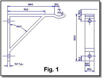
Note that the following shows a very simple part created for this explanation.
Step 1: The Question
The customer will typically have a simple question:
Will the bracket in this drawing (Fig. 1) support a 4800 Newton force?
Step 2: Refine the Question
Frequently, the initial question is too general, and it is almost always necessary to get more detail in order to model the part or process:
How will this part be used?
It will be attached to a rigid surface with two bolts. The force will act vertically downward on the hook.
What issues concern you most?
Can the diagonal support be reduced to save weight? Is the section near the hook thick enough to carry the load?
Step 3: Define Modeling Objectives
- An elastic material model will be sufficient for this case. It is not the designer's intention that the bracket should permanently deform under the given load.
- Solve for the equivalent stresses and determine the high stress areas.
- Recommend design improvements. Areas that are too highly stressed should be thickened. Areas that are not stressed can be thinned to reduce the material required.
Step 4: Formulate the Model
Use basic engineering principles to establish boundary conditions, such as which portions of the bracket should be fixed. Loading conditions must also be determined.
Fig. 2 shows the 4800 N force acting downward. The bolt holes should be constrained since the bolts will be rigidly connected to the wall. The back side of the bracket between the holes will be pressed against the wall by the action of the force, so that area should also be fixed. Note that for a more sophisticated analysis, the actual contact condition between the wall and bracket could be simulated.

Step 5: Create Geometry
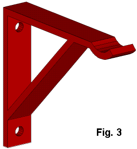
Using various tools, a three dimensional representation of the part is created (See Fig. 3). A two dimensional drawing was provided by the customer. If he can provide an electronic version of the design, such as an AutoCad drawing, DXF file, or an IGES file, it will speed up the process.
Step 6: Create Finite Element Mesh
The finite element method involves breaking an object into small (finite sized) pieces (elements), called a mesh. The solution for each individual element is relatively easy to determine, but each one depends upon all, or many, of the others. This is why a computer is required. There is an equation for each element, and each equation has as many terms as there are elements.
Fig. 4 shows the mesh for the part in question. There are 2221 elements in this model, they have parabolic interpolating functions, and a tetrahedral shape (four corners).

Step 7: Computer Solution
From the analyst's point of view, this is often the easiest step. The computer solution can run anywhere from a few seconds to many days or even weeks, though that is seldom practical. In this case the solution completed in 4 minutes and 14 seconds.
Step 8: Examine Results
There is a region of high stress near the hook, shown as red in Fig. 5. The diagonal brace and rear, vertical portion of the bracket are stressed very little as indicated by their blue color.

Step 9: Recommendations
Due to low stresses, the diagonal brace and vertical portions of the bracket could be reduced in size to save weight.
The thickness near the hook should be increased, the length of the hook extension decreased, or the diagonal moved outward to reduce stresses in the horizontal portion of the bracket.
These recommendations would be discussed with the customer. Most likely, further modeling would be performed to prove out the design changes.
Additional Benefits of Modeling
The results of a computer analysis are highly detailed and can be examined in many different ways. Information is available that could not be obtained through testing. For example, the interior of the bracket near the top hole is sectioned in Fig. 6. Slices are shown through the center of the bolt hole, an intermediate depth, and the surface, respectively.

In order to derive the most benefit from computer modeling, it is important that the analyst be involved as early in the design process as possible. Many potential design options can be evaluated, reducing the number of prototypes needed to arrive at a satisfactory product. This reduces the time, expense, and manpower required for product development.
Another use of modeling is in diagnostic investigation. Nonlinear Engineering can assist the customer in determining why a product or process is not performing as desired. An example would be determining the stress level in a machine component that has broken in the plant. A solution could be provided such as increasing a fillet radius, and what that radius should be. The important point is that the solution would be proven using simulation before any metal is cut
Conclusions
This page has concentrated on linear structural analysis. However,
Nonlinear Engineering also has expertise in highly nonlinear analysis such
as sheet
metal forming, automotive crash simulation, heat transfer including
solidification, fluid flow, and others. The
techniques described above apply equally well to these other disciplines.
|
Copyright © 2000 - 2018 Nonlinear Engineering, LLC |

|
Page last updated 05 July 2018 |